The key to a successful die casting is a good tool design, so it is vital that both the die caster and the customer are well-versed in die casting capabilities and how they fit with project requirements.
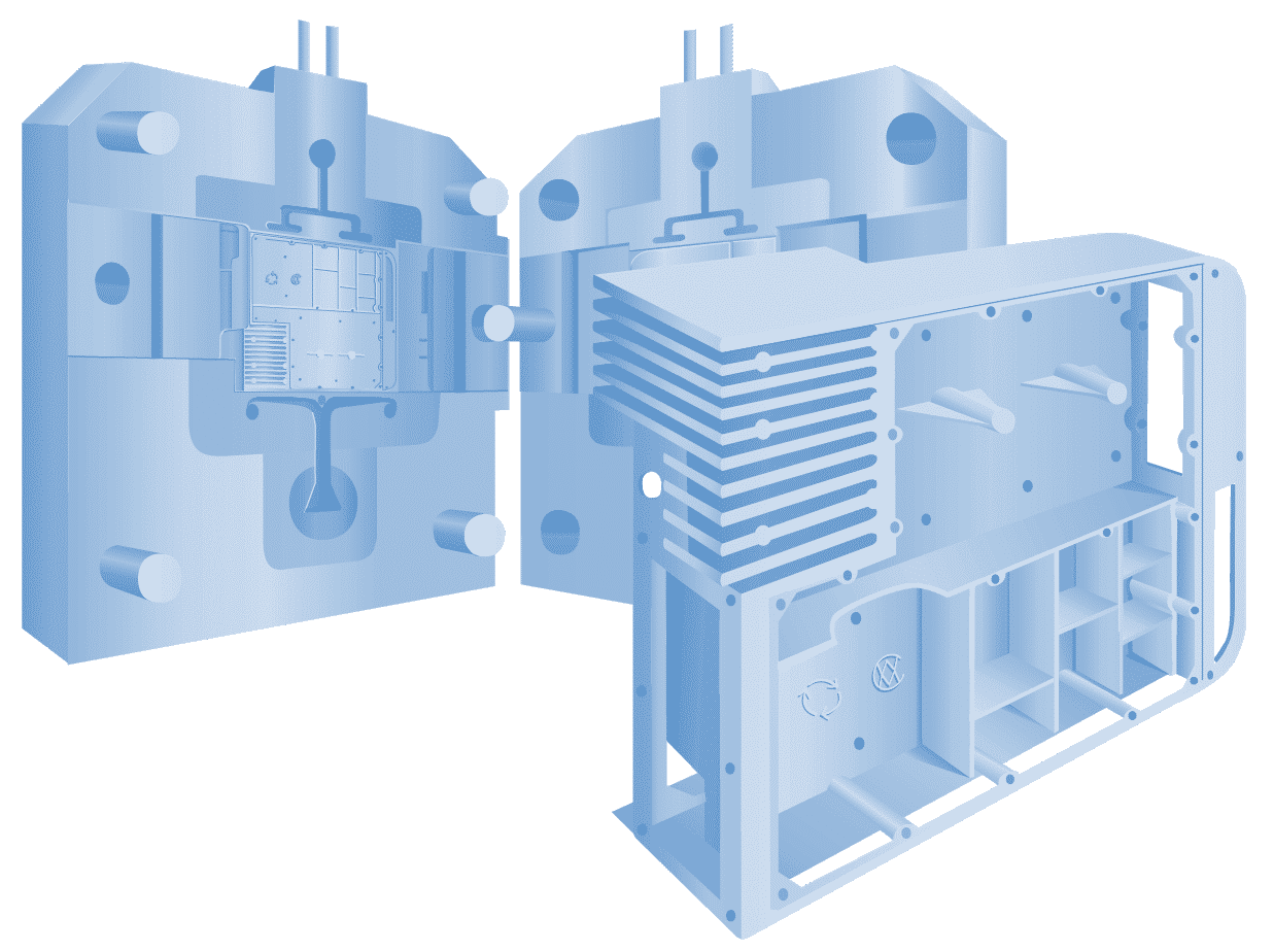
A die casting die is a custom-engineered, multi-part piece of equipment made from high quality, heat-treated steel. The tool is composed of two halves – a cover die (which is stationary) and the ejector die (which the die casting machine moves to meet the cover die). As soon as the two halves meet, the molten metal is injected into the tool, where it is held under pressure until it solidifies. After solidification, the metal is ejected, creating a nearly net shaped part within seconds.
Before a die is built, the customer first presents a concept or existing part to a die caster. A die cast engineer will assess the project from design to end product and work with the customer to optimize the part design for die casting. An initial discussion with the die caster may include topics such as: functional and cosmetic requirements, tolerances, annual and lifetime volume, alloy choice, mating parts, project timing, optimizing wall thickness, adding ribs, draft, and radius, etc. Download a checklist of common considerations from CWM’s Die Cast Design Center (DC²): NADCA Tooling Checklists for Die Casting Dies (2015).
Types of Die Casting Dies
Prototyping Dies
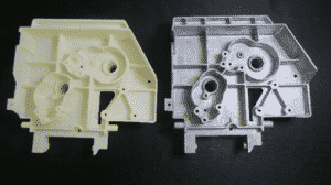
A fully-featured, custom production die is a significant investment, so a prototype die is often used to make a small number of castings to test the part in several different scenarios (with the end product, dimensional accuracy, etc.). Prototyping strategies include 3D printed parts, machined hogouts, or gravity castings, but these involve tradeoffs on the design, tolerances, and properties. A high pressure die casting prototype die is the best approach if you want the same properties, alloy, geometry, and process that will be in place for production.
Prototype die casting dies can be produced in shorter lead times and at less cost because they can utilize standardized components (such as an existing die base and other components), and pre-hardened, uncoated tool steels. They also require less engineering and may employ less efficient cooling or ejection techniques compared to other production methods. The tool will not last as long and the die will not run as efficiently as a typical production die, but this is a non-issue when you only need a small quantity of parts (1,000 or less). Design changes can be made faster and at less cost with a prototype die than would be the case on a custom, hardened/coated steel production die. Parts made from a prototype die are generally hand cleaned of flash, avoiding the lead time and cost of a trim die.
Production Dies
Production dies are used when all designs are finalized, approved, and the program is ready to “launch” into an actual run. These dies can have single or multiple cavities and the option of slides, depending on the design. Read more about slides below, under “Casting Features and Die Considerations”.
Trim dies: In addition to the production die cast die, CWM employs trim dies for high volume production. The trim die “trims” off the runner, overflows, and flash from the part, immediately after it is cast. Some trim dies only require an open/close function, and others need multiple stations, cam, or hydraulically-operated motions to successfully remove all of the flash. Occasionally, part geometry precludes the ability to completely remove flash with a trim die. In that case, custom trimming devices, mechanical or hand de-flashing strategies will be employed.
Unit Dies
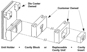
A unit die is a special type of production die. A common die-caster owned unit holder keeps the customer-owned cavity block or unit die with cavity insert intact. Single and double unit holders are common and come in a variety of sizes. Typical sizes of the cavity blocks that they hold are 8”x10”; 10”x12”; 12”x15”; or 15”x18”. Since unit dies employ generic components, they are often used for smaller, less complex parts with lower volume. Larger, multiple slide, complex geometry, and higher volume parts are generally better served with a complete custom die that is engineered specifically for that part and allows for maximum efficiency and control.
Die Components and Terms
Some of the more common die components and terms include cavities (or cavity inserts), parting lines, cores or core pins, slides or slide cores, ejector plates and ejector pins. A brief description of each follows:
Cavity Blocks or Cavity Inserts
These are the portions of the die casting die into which the part geometry is formed. There is the ejector cavity (sometimes called the core cavity) and the cover cavity. The cavity blocks are made of premium grade tool steel and are normally heat-treated to a very high hardness, then coated for lubricity and long life. Water cooling lines pass through the cavity blocks as do the ejector pins that are used to push the part off of the die. The cavity blocks are where most of the cost comes from, as generally this is where most of the custom design, engineering, and detailed machining is done.
Parting Lines
When the two die halves close, metal is injected into the cavity blocks and cooled in order to create the part. There is a line that forms on the part where the cover half and the ejector half meet called the “parting line.”
More information on the parting line can be found in the following blog, “Read Between the Lines: Parting Line Placement in Metal Die Casting Design”.
Cores or Core Pins
A “core” is the separate and replaceable part of the die that forms an internal feature of the casting. A core can be any shape, though circular is the most common (usually referred to as a “core pin”). A core may be fixed to the die cavity or to a slide, actuated through the mechanical opening/closing of the die, or by hydraulic cylinder or other means.
Slides or Slide Cores
A slide (or slide core) is the portion of the die that forms a feature of the casting, that cannot be made with the normal opening and closing of the die, but is required to move at some angle relative to the parting line (with the most common orientation being parallel to the parting line). The “slide” is the general term for the entire moving section, but a slide consists of multiple pieces (such as the slide front or tip, the wear plates, gibs, locks, carriers, etc.) and is generally water cooled. Slide core is the general term used for either a simple core pin that is moving in and out on some angle to the parting line or a pin within the larger slide mechanism (for example: a replaceable “slide pin” can be mounted in the slide to form a specific hole, where the rest of the slide face forms the outside surface of the part).
Angle pins and hydraulic cylinders are the most common motion sources that activate slides. Both sources of motion need to be designed into the tooling to avoid interference with part ejection/removal.
Angle pins are the more economical option because it is activated by the opening and closing of the die, and does not require hydraulics or switches, but is limited to shorter movements. The hydraulic method offers a wider range of options including pull direction, timing of the pulling, and length of pull. A die cast engineer can recommend the appropriate option based on the project.
Ejector Plates and Ejector Pins
Once a part has been cast and cooled, the halves open up and reveal the cast part. The part typically shrinks in size as it cools, remaining in the ejector half of the die. Ejector pins that are driven by a moving ejector plate are activated and used to push the casting off the die.
The ejector pin leaves a slight imprint on the casting, which indicates the placement of the pin should be in a non-cosmetic surface area of the casting that is not critical to the design (overflow, boss, bottom of a deep pocket, bottom of a rib, etc.). Ultimately, the number of pins, pin locations, and pin sizes are dependent on the configuration and size of the part, along with other requirements.
Contact a CWM Die Cast Engineer.
Our engineering team is prepared to answer any questions you may have about the die casting process, as it pertains to your project. Feel free to contact us directly at 630-595-4424, or e-mail us at sales@cwmtl.com in order to get in touch with the appropriate specialist.